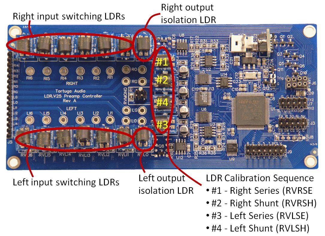
A V25 board is shown below with a full complement of single LDR modules installed for both input switching (used on/off signal switchers). The single LDR module has a 4-pin socket that plugs into simple 4-pin headers on the board.
There is no latching or detent mechanism to orient the module. It’s possible to plug a module into the board 4 different ways but only 1 is the correct way. You can tell which orientation is correct by aligning the white dot on the module with the matching white dot on the board next to each 4 pin LDR mounting header.
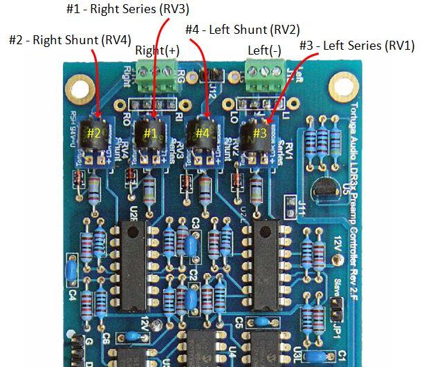
A V2 board is shown to the right with its four LDRs soldered in place. The subsequent V2.1 boards look identical but the single LDR modules are plugged in and not soldered.
Each V2/V25 board uses 4 single LDR modules. On the V25 board above, these are labeled #1 through #4. Each stereo channel uses 2 LDRs in a series/shunt configuration. Since there are 2 stereo channels, there are 4 primary LDR modules involved in audio volume control. Each LDR is individually controlled by a microcontroller on the controller board. The controller board uses stored calibration data to generate the resistance values needed for each volume step.
More information on LDRs and their use in Tortuga Audio products can be found here in our online product documentation.