
A removed quad plug-in LDR module is shown below next to a V4 preamp controller board. The quad LDR module plugs into the V4 (and V3) board using simple pin headers and sockets. There is no latching mechanism and the module relies on friction to stay put. It’s possible to plug the module into the board incorrectly so be mindful of the module orientation and pin alignments.
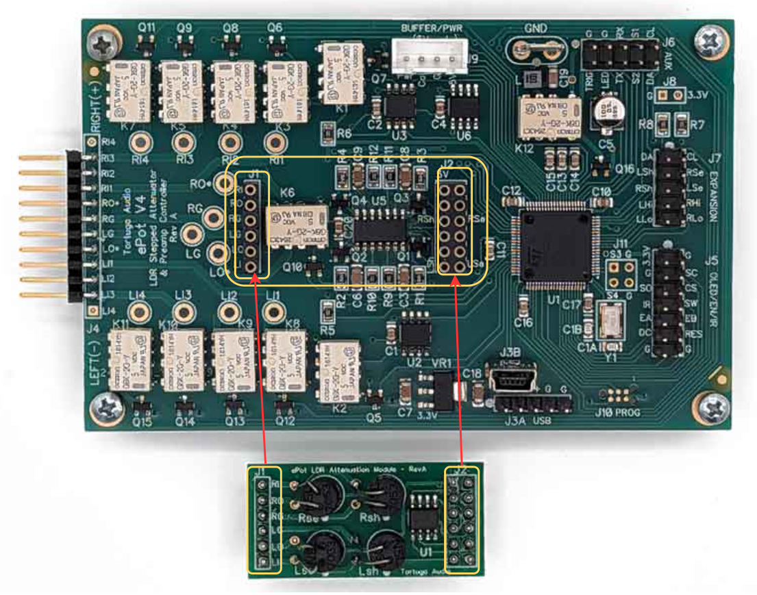
Each quad LDR module has 4 embedded LDRs plus two pin headers that plug into corresponding sockets on the V3 & V4 boards. Earlier versions of the quad LDR module had an EEPROM memory chip. V3 boards must use the earlier version with the EEPROM chip. V4 boards can use any version.
The quad LDR module handles both stereo channels. Each channel uses 2 LDRs in a series/shunt configuration. Each LDR is individually controlled by the microcontroller located on the V3 or V4 board. The controller board uses stored calibration data to generate the resistance values needed for each of the 100 volume steps. The V3 uses the EEPROM chip in the quad module whereas the V4 board uses a different EEPROM memory chip located on the V4 board.
The LDR attenuation module can be re-calibrated as needed and can be re-configured for any impedance setting from 1k to 99k with 20k or 50k being the typical fixed default impedance level for setting #1. This is only possible with the Max and not the Mini. The Mini does not have the built-in ability to calibrate its LDR module. For this reason you must specify the fixed impedance of the LDR attenuation module when purchasing one for a Mini controller board.
More information on LDRs and their use in Tortuga Audio products can be found here in our online product documentation.
